Fleet Fueling Design Guide
Technical reference for site planning, code compliance, and installation requirements.
Note: Aviation and Power Generation applications have separate design guides.
Application Types
Private/Fleet Fueling
Most common SmartTank application
- Commercial fleets
- Municipal vehicles (DPW, police, fire)
- Industrial facilities
- Construction companies
- Airports (non-public)
- Farms and agricultural
- Generator fuel systems
- Dispenser at tank - no remote piping
- Simpler permitting requirements
- No dispenser island construction
- No underground leak detection
- Lower total installed cost
Retail Fueling
Public gas station applications
- Truck stops
- Convenience stores
- Marinas (public)
- Cardlock stations
Retail applications require dispenser to be 50' minimum from tank per NFPA 30A. This requires underground or above-grade piping, leak detection, dispenser island construction, and more.
Separation Distance Requirements
Minimum distances from tanks to buildings, property lines, and other exposures. Always verify with your Authority Having Jurisdiction (AHJ) as local amendments may apply.
NFPA 30 / NFPA 30A - Protected Tanks (UL 2085)
Protected aboveground tanks meeting UL 2085 receive significant distance reductions.
| Tank Capacity (gallons) | To Buildings | To Property Line | To Public Way | To Dispenser |
|---|---|---|---|---|
| Up to 6,000 | 5 ft | 5 ft | 5 ft | 0 ft* |
| 6,001 - 12,000 | 5 ft | 5 ft | 5 ft | 0 ft* |
| 12,001 - 20,000 | 5 ft | 5 ft | 5 ft | 0 ft* |
| 20,001 - 30,000 | 10 ft | 5 ft | 5 ft | 0 ft* |
*For private fueling. Retail requires 50 ft minimum to dispenser per NFPA 30A.
NFPA 30 - Unprotected Tanks (UL 142)
Standard double-wall tanks without fire rating require greater separation.
| Tank Capacity (gallons) | To Buildings | To Property Line | To Public Way |
|---|---|---|---|
| Up to 275 | 5 ft | 5 ft | 5 ft |
| 276 - 750 | 10 ft | 5 ft | 5 ft |
| 751 - 12,000 | 15 ft | 5 ft | 5 ft |
| 12,001 - 30,000 | 25 ft | 5 ft | 5 ft |
Tank-to-Tank Spacing
Minimum Spacing Requirements
| Condition | Minimum Distance |
|---|---|
| Between adjacent tanks (shell to shell) | 3 feet |
| Between tank groups | Per NFPA 30 Table |
Multi-Tank Installations
For multi-tank installations, maintain minimum 3' shell-to-shell spacing per code requirements. Contact SmartTank Engineering for multi-tank system design assistance.
Concrete Pad & Site Preparation
Concrete Pad Specifications
| Pad Size | Minimum 24" larger than tank footprint |
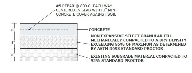
| Concrete Thickness | 8 inches minimum in all locations |
| Granular Fill | 8 inches non-expansive select fill, compacted to 95% per ASTM D698 |
| Subgrade | 8 inches existing material compacted to 95% Standard Proctor |
| Concrete Strength | f'c = 4,000 PSI, Grade 60 |
| Reinforcement | #5 rebar @ 8" O.C. each way, centered in slab per ASTM A615 |
| Rebar Cover | 3" minimum against soil |
| Surface Finish | Heavy broom finish |
| Surface Flatness | Planar within 1/16" in 8'-0" |
| Tank Anchors | Manufacturer supplied, 12mm concrete anchor bolts |
- Surface must be planar within 1/16" in 8'-0" to prevent point loading
- Slab must be placed on free-draining soil or crushed stone compacted to 95% Proctor
- Guard rail or bollards required with no opening greater than 48" between them
Concrete Pad Cross Section
Tank Pad Dimensions - Plan View
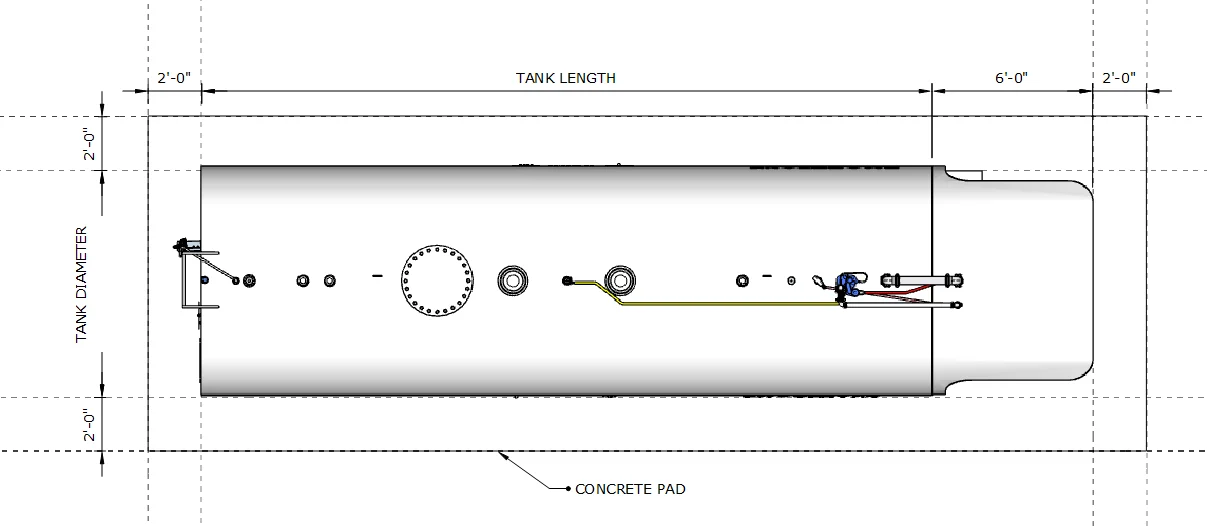
Concrete pad extends 2'-0" beyond tank footprint on all sides. Platform/canopy area adds 6'-0" to overall pad length.
Tank Anchoring
Tanks in flood-prone areas must be anchored to prevent flotation. An empty or partially filled tank can float when submerged in floodwater.
Buoyancy Calculation
The buoyant force on a submerged tank equals the weight of water displaced:
Buoyant Force (lbs) = Tank Volume (gallons) × 8.34 lbs/gallon
This is the upward force when the tank is fully submerged in water. The tank will float if this force exceeds the combined weight of the tank and its contents.
Example Calculations
| Tank Size | Buoyant Force (empty tank submerged) | Approximate Tank Weight | Net Uplift Force |
|---|---|---|---|
| 1,000 gallon | 8,340 lbs | ~2,500 lbs | ~5,840 lbs |
| 2,500 gallon | 20,850 lbs | ~4,500 lbs | ~16,350 lbs |
| 5,000 gallon | 41,700 lbs | ~7,000 lbs | ~34,700 lbs |
| 10,000 gallon | 83,400 lbs | ~12,000 lbs | ~71,400 lbs |
Anchoring Method
Tank Saddle Anchor Points
Each tank saddle is equipped with two 1" diameter holes for anchor bolts. A typical two-saddle tank has four anchor points total.
Recommended Procedure
- Set tank on concrete pad in final position
- Mark anchor hole locations through saddle holes
- Drill holes using appropriate Hilti anchor specifications
- Install 3/4" concrete anchor bolts
- Torque to manufacturer specifications
Pre-installing anchor bolts in the concrete pad before tank delivery is not recommended. Field conditions, tank positioning, and saddle hole alignment make it nearly impossible to achieve proper fit with pre-set bolts.
When is Anchoring Required?
- Locations in FEMA-designated flood zones
- Sites with history of flooding or high water table
- Areas subject to storm surge or coastal flooding
- When required by local AHJ or building code
- Insurance or SPCC Plan requirements
Consult with SmartTank Engineering for anchor bolt sizing and pullout calculations specific to your tank size and flood conditions.
Motor Vehicle Impact Protection
Design guide for protecting aboveground storage tanks from vehicle impact.
Common Barrier Types
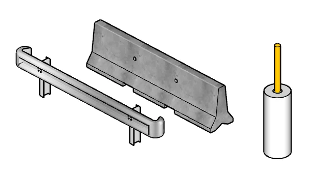
Left to right: Steel Guardrail, Precast Concrete "Jersey" Barrier, Pipe Bollard
There are three types of barriers commonly used: Guard Rail, Precast Concrete "Jersey" Barriers, and Pipe Bollards. Sometimes a mix of those is used. Guard Rail is least expensive. Pipe Bollards are the most expensive. Pipe Bollards should be 5' from the tank and spaced no more than 4' apart. 4" and 6" Bollards are common.
Steel Guardrail
- ✓ Highway-style W-beam guardrail
- ✓ Continuous protection
- ✓ Snow plow compatible
- ✓ Easy to repair/replace sections
- ✓ Galvanized for corrosion resistance
- Least expensive option
Precast Concrete "Jersey" Barriers
- ✓ Concrete traffic barriers
- ✓ Temporary or permanent installation
- ✓ Heavy vehicle impact rated
- ✓ Can be pinned together
- ✓ No foundation required
- Moderate cost
Steel Pipe Bollards
- ✓ 4" and 6" diameters common
- ✓ 4' maximum spacing between bollards
- ✓ 5' setback from tank recommended
- ✓ Yellow plastic bollard covers
- ✓ Concrete foundation required
- Most expensive option
Site Layout Options
Choose a layout based on your site requirements, traffic flow, and fueling volume needs.
Perpendicular Layout with Guardrail
Single fueling position with guardrail protection surrounding tank pad.
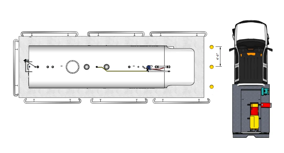
Perpendicular Layout with Bollards
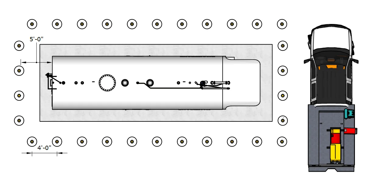
Single fueling position with bollard perimeter. 5'-0" setback from tank, 4'-0" spacing between bollards.
Parallel Layout - Two Fueling Positions
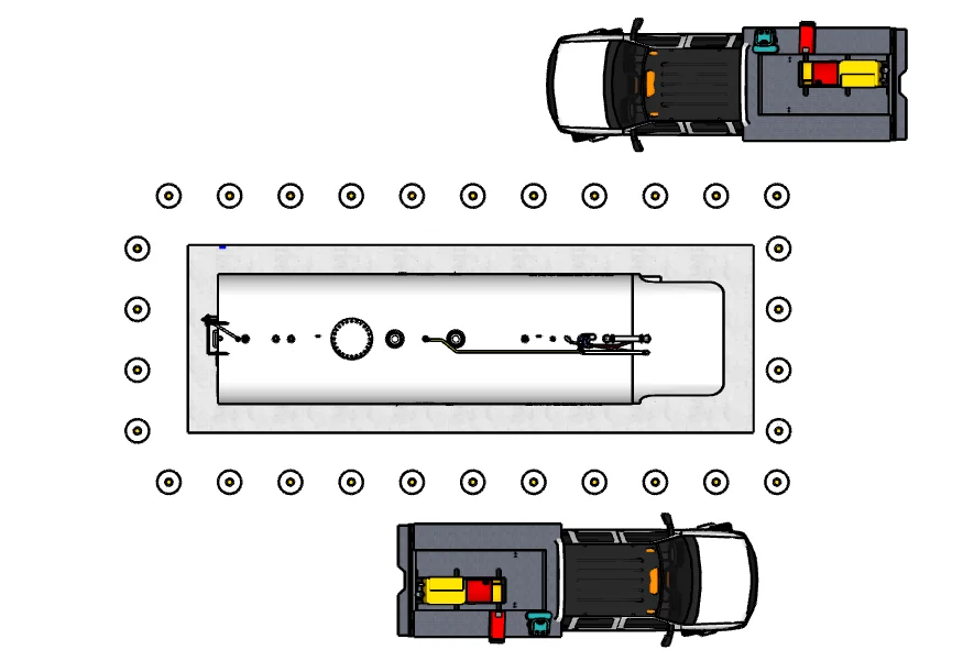
Parallel fueling lanes on both sides of tank allow two vehicles to fuel simultaneously. Ideal for higher-volume fleet operations.
Four Fueling Positions - Maximum Throughput
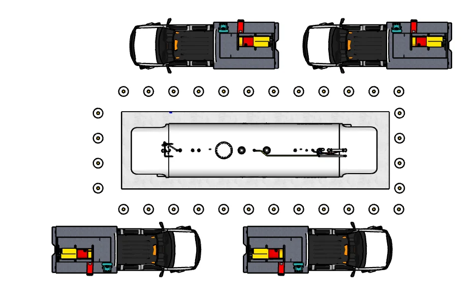
Four-position layout with dual-hose dispensers at each end serves two vehicles per side simultaneously. Maximum throughput for high-volume operations.
Removable Bollard Detail
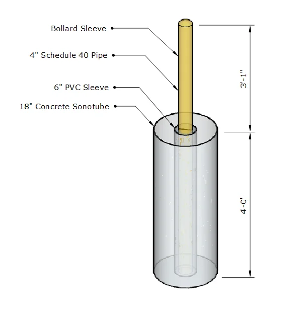
Placing a 4" pipe bollard in a 6" PVC pipe and backfilling it with sand allows for easy bollard removal and replacement should it become damaged.
Construction Details
- Steel Pipe Bollard: 4" Schedule 40 steel pipe
- PVC Sleeve: 6" PVC pipe cast into concrete
- Sand Backfill: Fills void between pipe and sleeve
- Concrete Foundation: 18" diameter sonotube
- Embedment Depth: 4'-0" below grade
- Height Above Grade: 3'-1"
- Bollard Sleeve: Yellow plastic cap for visibility
Safety Equipment Requirements
Required safety equipment per NFPA 30, NFPA 30A, and IFC for aboveground fuel storage installations.
Fire Extinguisher Requirements (NFPA 30)
| Type | ABC dry chemical or BC rated for flammable liquids |
| Minimum Rating | 20-B:C minimum (40-B:C recommended) |
| Size | 10 lb minimum (20 lb recommended) |
| Location | Within 50' of dispenser, visible and accessible |
| Mounting | 3-5' above grade, weather protected cabinet |
| Quantity | Minimum 1 per tank, additional per AHJ |
| Inspection | Monthly visual, annual professional service |
Emergency Stop (E-Stop)
| Function | Immediately shuts off pump and power to dispenser |
| Location | Within 25' of dispenser, clearly visible |
| Signage | "EMERGENCY STOP" sign required |
| Color | Red button on yellow background |
| Reset | Manual reset required after activation |
Required Signage
| No Smoking | Visible from all approaches |
| Flammable | NFPA 704 diamond or equivalent |
| Emergency Stop | At E-Stop location |
| Emergency Contact | Fire department, facility contact numbers |
| Operating Instructions | At dispenser location |
| Product Identification | DIESEL, GASOLINE, etc. at fill port and dispenser |
Electrical
We pre-wire our tank systems down to junction boxes and provide a Site Manager control panel for easy point-to-point field wiring. Our designs are complete with:
- Emergency stop disconnects
- Service disconnects
- Motor starters
- Sub panel
- Surge suppression
- Fuel management system power
- Submersible pump running light
- Dispenser power
- Dispenser lighting power
- Electronic level gauging integration
- Leak detection system integration
- Hose reel rewind motors
- Emergency phones
- Site security integration
Each system is customized to your facility's needs.
System Overview
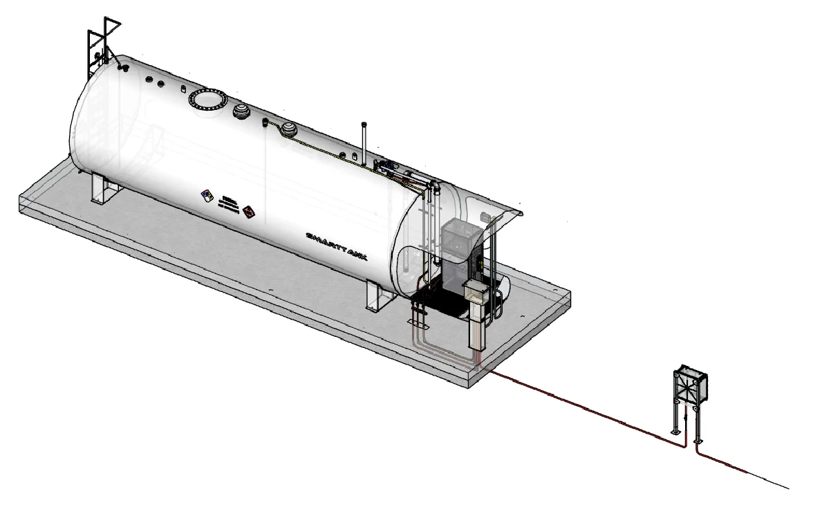
Complete tank system with Site Manager control panel located 20-100' from dispenser. Underground conduit keeps installation tidy and eliminates tripping hazards.
Site Manager Control Panel
| Power Requirements | 240V single phase, typically less than 60A |
| Enclosure | NEMA 4X outdoor rated |
| Location | 20-100' from dispenser (contains E-Stop) |
| Listing | UL Listed |
| Code Compliance | Meets NEC requirements |
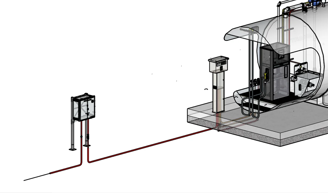
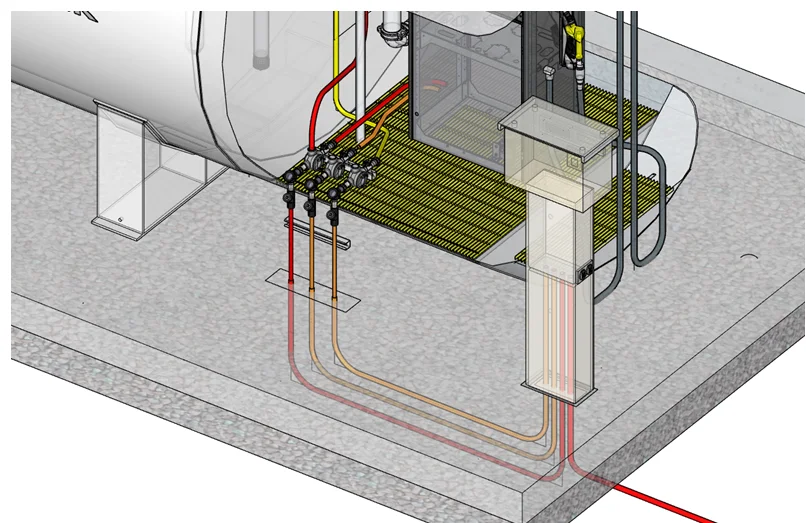
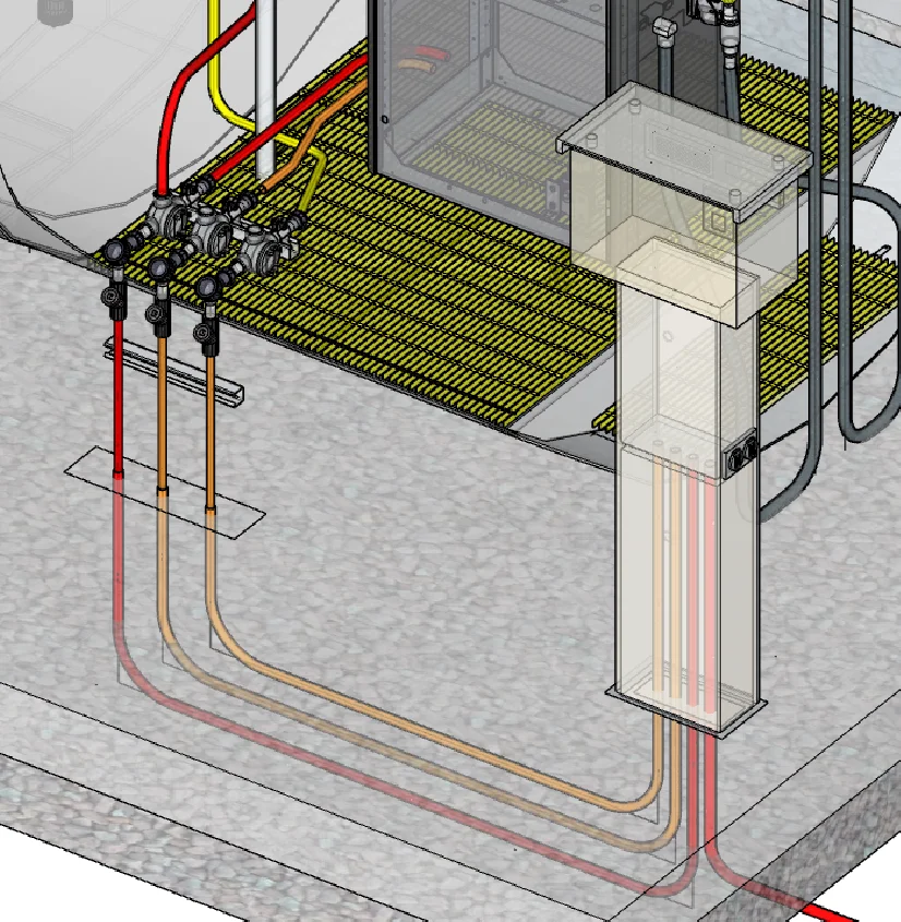
Conduit Routing Details
We provide conduit layout drawings with conduit stub-up locations in the concrete pad. This keeps installations tidy and avoids conduit runs across the concrete that can become tripping hazards.
- Explosion proof conduit is not watertight by design and should be protected from the elements—we locate it under the canopy
- Rigid metal conduit is required to provide grounding
- Our installation drawings are very complete with step-by-step instructions for the electrician
Remote Dispensers
Occasionally our clients require remote dispensers separate from the tank location. These custom configurations involve additional engineering considerations.
Remote Dispenser Applications
- ✓ Underground piping systems
- ✓ Leak detection systems
- ✓ Dispenser island forms
- ✓ Canopy structures
- ✓ Fire suppression systems (where required)
- ✓ Marina dispensers
- ✓ Satellite dispensers
40 Years of Experience
SmartTank has four decades of experience designing complex remote dispenser systems. We provide the parts and expertise to make sure your project is designed right.
Contact Us for Custom Systems
Discuss your custom fueling system needs with our engineering team.
Phone: 888.708.5423
Email: [email protected]
Web: www.fuel-tanks.com
Retail Fueling Requirements
Key Differences from Private Fueling
| Requirement | Private Fueling | Retail Fueling |
|---|---|---|
| Dispenser Location | At tank (0' separation) | Minimum 50' from tank |
| Piping to Dispenser | Not required | Underground or above-grade |
| Piping Leak Detection | Not required | Required for underground |
| Dispenser Island | Not required | Concrete island required |
| Dispenser Bollards | Not required | Required |
| Dispenser Containment | Not required | Sump required |
| Canopy | Optional (on tank) | Typically over dispenser island |
| Estimated Additional Cost | - | $50,000 - $150,000+ |
Contact Engineering for Retail Systems
Retail fueling systems require custom engineering including site-specific piping design, dispenser island layout, leak detection system specification, vapor recovery (where required), and point-of-sale integration.
Phone: 888.708.5423
Email: [email protected]
Web: www.fuel-tanks.com
Secondary Containment
Built-In Secondary Containment
All SmartTank dual-wall systems include:
- ✓ 100% containment capacity (full inner tank volume)
- ✓ Sealed construction—no rain accumulation
- ✓ Continuous interstitial monitoring
- ✓ Mechanical leak detection gauge
- ✓ No drain valves to maintain
- ✓ No standing water issues
- ✓ No debris accumulation
Problems with Containment Dikes
Tertiary containment creates maintenance issues:
- ✗ Standing water causes saddle corrosion
- ✗ Drain valves left open defeat purpose
- ✗ Drain valves clog with dirt/debris
- ✗ Requires regular inspection/pumping
- ✗ Additional construction cost
- ✗ Takes up valuable site space
- Environmentally sensitive areas (near waterways, wetlands)
- Specific state or local regulations
- Some insurance requirements
Consult your AHJ and environmental regulations for site-specific requirements.
SPCC Requirements
When is an SPCC Plan Required?
Your facility requires an SPCC Plan if it meets ALL of these criteria:
- Stores oil (petroleum fuels, used oil, hydraulic oil, etc.)
- Total aboveground storage capacity exceeds 1,320 gallons (counting all containers 55 gallons or larger)
- Could reasonably discharge to navigable waters or adjoining shorelines (including via storm drains)
SPCC Plan Tiers
The EPA divides facilities into tiers based on storage capacity, which determines certification requirements:
| Tier | Capacity Requirements | Certification |
|---|---|---|
| Tier I Qualified Facility | Total capacity ≤ 10,000 gallons No single container > 5,000 gallons No significant spill history |
Self-certified by owner/operator Can use EPA template |
| Tier II Qualified Facility | Total capacity ≤ 10,000 gallons Individual containers may exceed 5,000 gallons No significant spill history |
Self-certified by owner/operator Must prepare own plan per 40 CFR 112.7 |
| Tier III (PE Certified) | Total capacity > 10,000 gallons OR significant spill history |
Must be certified by a licensed Professional Engineer (PE) |
Key SPCC Plan Elements
- Facility description and oil storage inventory
- Site diagram showing tanks, drainage, and water bodies
- Spill predictions and containment analysis
- Secondary containment documentation
- Overfill prevention procedures
- Inspection and testing schedules
- Personnel training requirements
- Spill response procedures
- Security measures
- Five-year plan review requirements
SmartTank SPCC Plan Services
SmartTank can provide SPCC Plans for your fuel storage installation. Our plans include all required elements and are prepared to meet federal requirements.
Phone: 888.708.5423
Email: [email protected]
Web: www.fuel-tanks.com
- SPCC Plans must be kept on-site and available for inspection
- Plans must be reviewed and amended when facility changes occur
- Some states have additional requirements beyond federal EPA regulations
- Spills must be documented and reported per plan requirements